Infinitesimal Offset Meshes
In PathEngine, we do a lot of stuff on the surfaces of ground meshes.
One example is tracking the ground position for a moving agent, which is implemented as traversal along a 2D line through a mesh.
When coding stuff like this the need to check and handle special case conditions like vertex crossings, or traversal exactly along an edge, can add a lot of complexity.
In this post I talk about a technique we use in PathEngine, based on an infinitesimally offset mesh model, to eliminate these kinds of special case conditions and simplify our mesh based geometry.
2.5D meshes
The core collision and pathfinding for PathEngine operates in a kind of '2.5D' space.
Points on ground meshes are projected onto the horizontal plane.
Mesh positions are represented as 2D (horizontal) coordinates but with a mesh face reference to disambiguate positions in overlapping ground layers (to support stuff like bridges and multistory buildings).
Traversal special cases
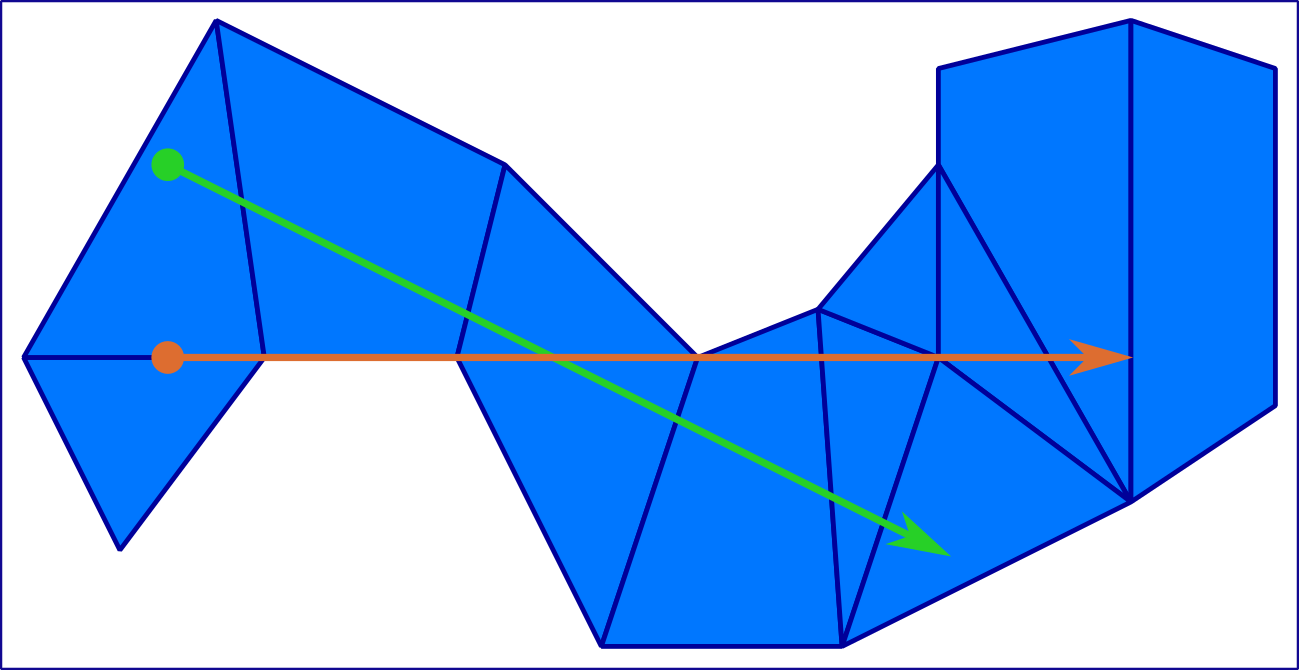
So one thing we need to do is to compute traversals through the mesh. Let's look at what's involved in this.
The traversal will usually start in a face, cross zero or more edges, and end in a face, but we may also encounter a number of other special case conditions:
- traversal start or end exactly on a mesh edge,
- traversal start or end exactly on a vertex,
- vertex crossings,
- traversal exactly along an edge
It's possible to just go ahead and write the code to check and handle each condition explicitly. That means special case code for each of three possible traversal start conditions (in face, on edge, on vertex), first of all.
But traversal exactly along an edge probably needs to be handled differently from traversal across an edge.
And we'll also need to check for three possibilities at the bounding edge or vertex, in a number of different state transition cases:
- traversal ends before the bound
- traversal ends exactly on the bound
- traversal continues past the bound
It's not too hard to write code to handle these various traversal states and boundary cases, and it's even possible to keep the code for this relatively manageable for testing and debugging, but this complexity can be a bit surprising given the simplicity of our requirements. All we're actually doing is following a 2D line through the mesh.
And there's already some kind of 'combinatorial complexity' going on, where each of multiple states needs to check for several possible bound conditions. My experience is that this combinatorial effect can lead to things can getting a lot uglier, very quickly, when we move on to cases where we need to solve more complicated requirements.
Some things that complicate the situation, in PathEngine:
- the need to do a variety of other things at the same time as a traversal (e.g. tracking some traversal related state)
- the need to work with traversals that start or end at intersections with other lines (instead of simple points)
- different traversal types, such as unbounded raycasting
- optimisation
Not just traversals
This doesn't just relate to traversals, of course. There a bunch of other stuff we need to do which involve the same kind of special case conditions, but with more complicated requirements, for example:
- position translation between different (overlaid) mesh representations
- flood fill through the mesh inside polygonal bounds
- detection of overlap between projected shapes
- combination of projected shapes, and generation of a combined boundary representation
And another complication relates to the problem of assigning elements to mesh faces. For elements that land exactly on edges or vertices, which face do we assign (or index the element under)?
Exception rather than rule
In all of the above, exactly on vertex and edge special cases are actually an exception rather than the rule. Most of the time points won't fall exactly on edges or vertices, and most of the time lines will just cross edges.
And the special case handing code doesn't really give us anything, in the sense that if the special case situations didn't occur then we could achieve exactly the same high level behaviours, but without all these special case checks.
Is there a way for us to eliminate the special cases?
Integer grid
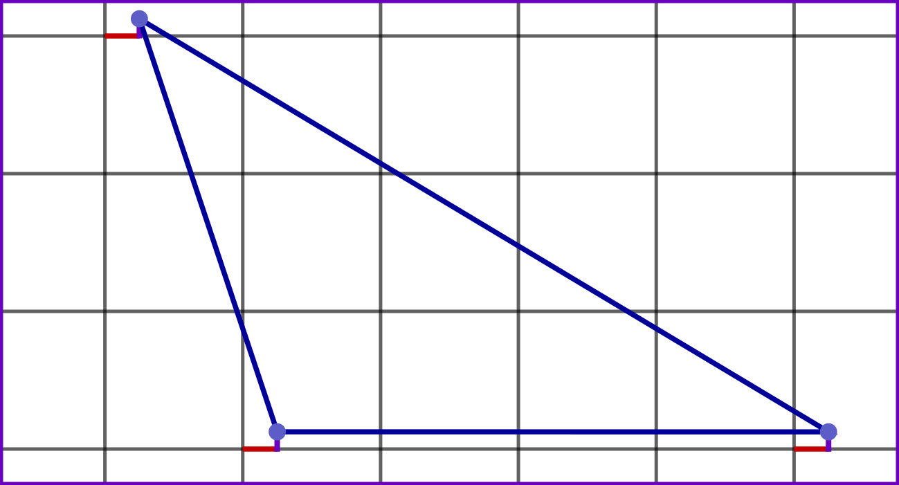
In PathEngine, vertex x and y coordinates are integers, and you can think of our mesh vertices as being 'snapped' to a fixed, discrete grid. So we can picture a (small!) triangular mesh face as follows:
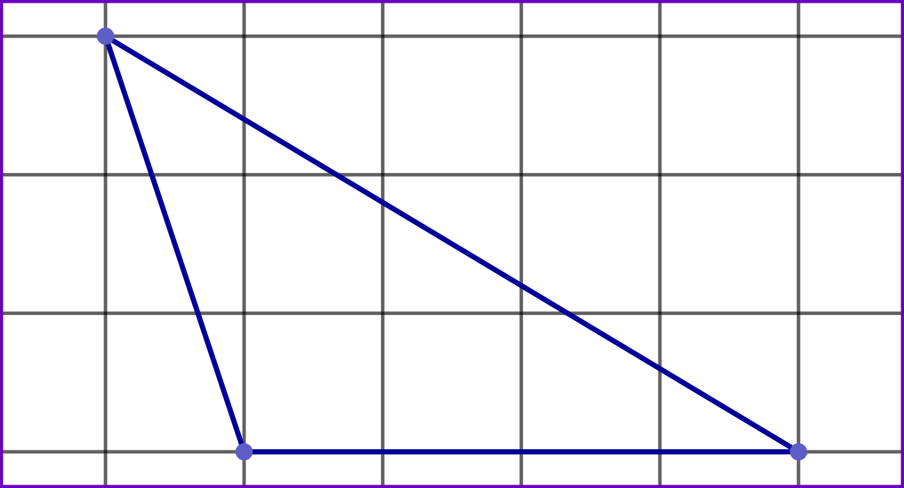
Each vertex falls exactly on a grid intersection, and each mesh edge is a line between two grid intersections.
(We use integers because floating point coordinates just aren't suitable for this kind of situation! This is something I've discussed in a number of places, although not yet on this blog. See this article on AIGameDev, for more on this.)
Normally, all of our geometry (including things like traversal line endpoints) is placed on exactly the same grid. But it doesn't have to be this way.
Infinitesimal offsets
The solution is to offset our mesh vertices very slightly.
Imagine pushing a mesh vertex very slightly to the right (towards increasing x), first of all. Actually, let's move it an infinitesimal amount to the right.
What we're trying to do is to make it impossible for lines (on the integer grid) to exactly cross our offset vertex.
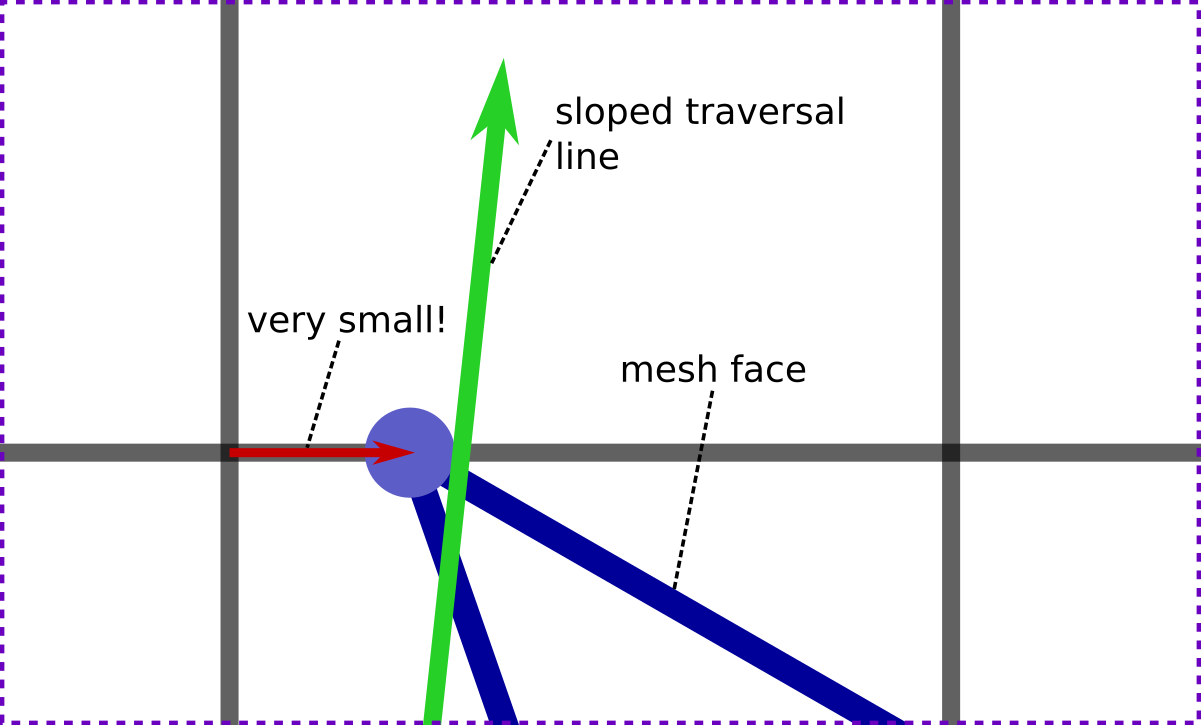
This single offset already nearly does what we need. We've moved the vertex off of vertical grid lines, and sloping lines which don't cross the intersection exactly will always have some finite offset from this intersection, and can't cross the vertex either.
But horizontal lines, with the same y coordinate, can. So let's also add another offset, to move the vertex very slightly upwards (towards increasing y and the top of the page in the diagrams). This time, we'll move the vertex an even smaller distance. Let's make the amount of this second, vertical, offset, infinitely smaller than the amount of the first offset:
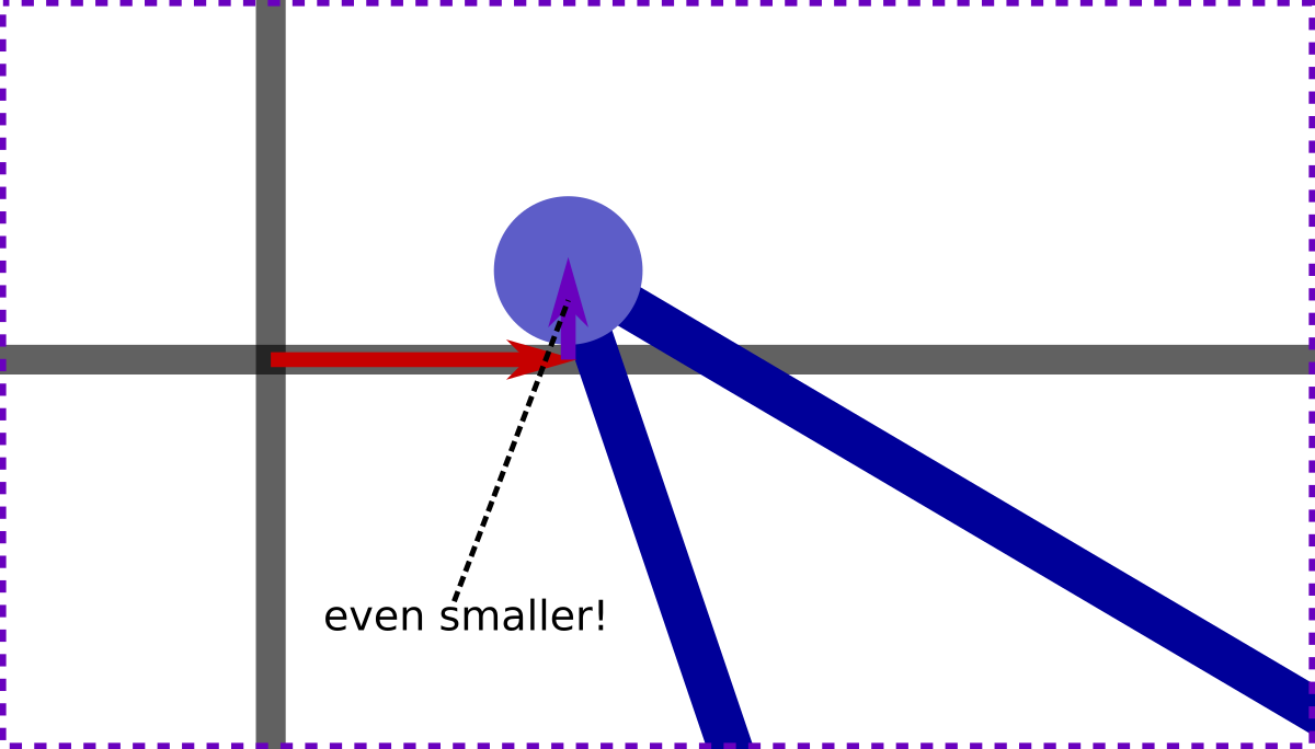
Now horizontal lines can't cross the vertex, either, and we're ready to go! Let's go ahead and apply these offsets to all our mesh vertices:
The offsets aren't drawn to scale here, but you get the idea.
Note that the mesh is still on an integer grid (not drawn), but with this grid slightly offset from the 'normal' grid.
Un-offset lines can't cross offset vertices, and this also works in reverse, so mesh edges can't cross un-offset points either. And, then for our traversal line (which we'll leave on the un-offset grid):
- it's not possible for either line endpoint to fall exactly on a mesh vertex or mesh edge
- (so traversal start and end points must each be in a face)
- and it's not possible for the traversal line to exactly cross a vertex
- (so the traversal can only cross edges)
So this gets rid of all those special case conditions, then.
If we can implement this infinitesimally offset 'mesh model' then we can implement a traversal with only edge crossings, and a binary edge crossed check.
Side tests
How do we actually apply these infinitesimal offsets, in practice?
The key lies in an atomic side test operation, which can be implemented as follows:
enum eSide
{
    SIDE_LEFT = -1,
    SIDE_CENTRE = 0,
    SIDE_RIGHT = 1,
};

eSide
SideOf(cPointDiff lhs, cPointDiff rhs)
{
    tSigned64 lhs64 = rhs.x();
    lhs64 *= lhs.y();
    tSigned64 rhs64 = rhs.y();
    rhs64 *= lhs.x();
    if (lhs64 < rhs64)
    {
        return SIDE_LEFT;
    }
    if (lhs64 == rhs64)
    {
        return SIDE_CENTRE;
    }
    return SIDE_RIGHT;
}
cPointDiff represents the difference between two points in 2D, i.e. this is a 2D vector.
This atomic side test operation is pretty much all we need, in terms of geometry, for something like our line traversal. We can use this, for example, to test which side of a mesh edge for some point:
eSide
SideOfMeshEdgeForPoint(const cMesh& mesh, cEdge edge, cPoint testPoint)
{
    cPointDiff edgeAxis = EdgeEnd(mesh, edge) - EdgeStart(mesh, edge);
    cPointDiff testOffset = testPoint - EdgeStart(mesh, edge);
    return SideOf(edgeAxis, testOffset);
}
Or, to test which side of a line for some vertex:
eSide
SideOfLineForMeshVert(const cMesh& mesh, cPoint lineStart, cPoint lineEnd, cEdge edgeFromVertex)
{
    cPointDiff lineAxis = lineEnd - lineStart;
    cPointDiff testOffset = EdgeStart(mesh, edgeFromVertex) - lineStart;
    return SideOf(lineAxis, testOffset);
}
What does infinitesimal mean?
Mathematically speaking there are different kinds of infinitesimal numbers. What do we mean by 'infinitesimal' here?
Well, we're using our infinitesimal offsets for quite a specific purpose, and so we can give a very straightforward and concrete meaning to the word infinitesimal in this context.
Lets call the amount of the first offset iota_1, and the amount of the second offset iota_2.
So, iota_1 is then just some amount that's too small to make any difference to side tests, except in cases where the two vectors are exactly on line.
And iota_2 is an amount that's too small to make any difference to side tests, except in cases where two vectors and any iota_1 offsets are all exactly on line.
Side note: because our points and lines are on a discrete grid, and because there's a maximum coordinate range for these points, it's actually possible to calculate very small finite values that fit these constraints, and mathematical infinity is not strictly required. But that's can kind of beside the point, and there's certainly no need for us to actually calculate these very small values.
We can go directly from these definitions of iota_1 and iota_2 to some working code.
Side with infinitesimals
This can be implemented as a kind of cascade of side tests. The iota_1 offset is applied only if an initial (vanilla) side test gives SIDE_CENTRE, and then the iota_2 offset is applied only if we still have SIDE_CENTRE after the iota_1 offset has been applied:
eSide
SideOfLineForMeshVert(const cMesh& mesh, cPoint lineStart, cPoint lineEnd, cEdge edgeFromVertex)
{
    cPointDiff lineAxis = lineEnd - lineStart;
    cPointDiff testOffset = EdgeStart(mesh, edgeFromVertex) - lineStart;
    eSide result = SideOf(lineAxis, testOffset);
    if(result == SIDE_CENTRE)
    {
        result = SideOf(lineAxis, cPointDiff(1, 0));
        if(result == SIDE_CENTRE)
        {
            result = SideOf(lineAxis, cPointDiff(0, 1));
            assertD(result != SIDE_CENTRE);
        }
    }
    return result;
}
And we can do essentially the same thing to SideOfMeshEdgeForPoint() (but with the offsets applied in reverse).
Note that these functions should now never return SIDE_CENTRE, which is what, fundamentally, collapses all those special case checks.
Any code that calls the modified version of SideOfLineForMeshVert() only has to handle two, instead of three possible return values.
Optimisation
I'm not going to talk much about optimisation, except just to note that we don't actually need to do full side tests for the axis-aligned offset vectors.
Based on this observation we can change SideOfLineForMeshVert() as follows:
eSide
SideOfLineForMeshVert(const cMesh& mesh, cPoint lineStart, cPoint lineEnd, cEdge edgeFromVertex)
{
    cPointDiff lineAxis = lineEnd - lineStart;
    cPointDiff testOffset = EdgeStart(mesh, edgeFromVertex) - lineStart;
    eSide result = SideOf(lineAxis, testOffset);
    if(result == SIDE_CENTRE)
    {
        if(lineAxis.y() != 0)
        {
            return lineAxis.y() > 0 ? SIDE_RIGHT : SIDE_LEFT;
        }
        assertD(lineAxis.x() != 0);
        return lineAxis.x() > 0 ? SIDE_LEFT : SIDE_RIGHT;

    }
    return result;
}
Geometry at edge of mesh
If we update the traversals diagram at the start of the blog with the new mesh model, then we can see that the 'special cases' traversal now actually exits the mesh:
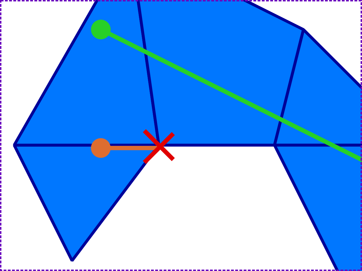
So changing the mesh model can change the results for geometry at the edge of the mesh, and some points that may have been considered 'inside' the mesh may now fall outside.
It was a compatibility breaking change for PathEngine when we switched to this model, for this reason, with clients needing to update things like stored agent positions when updating to SDK releases after this change.
Once the new mesh model is in place however, everything is consistent, as long as we stick with the new model. (Note that reversing the special cases traversal, i.e. traversing back from the endpoint, also exits the mesh.)
Points placed 'at a vertex'
On a related point, it's important to bear in mind that you cannot now place non-offset points 'at a vertex', for example to start a traversal from a vertex.
You can set the point coordinates for your traversal start point to be the same as the vertex coordinates, but the mesh offsets will put this start position outside the mesh, in many cases.
(It's important to be quite rigorous and apply the offsets consistently, or stuff will break!)
If you need to do things like this (traversing from a mesh vertex), then other mesh models may be more appropriate for this task.
When to use the technique
As long as the geometry needing to be located inside the mesh remains distinct from the mesh geometry itself, this is a great technique (and can really simplify your code).
More generally, I think this can be applied as long as you have some kind of geometric framework (the mesh, in our case), together with geometric elements being placed in or against that framework, but with the two sets of elements remaining distinct.
The technique is particularly useful for PathEngine because we provide pathfinding around obstacles placed on top of ground meshes, and this means working with boundary geometry inside the mesh, but I think it can also be useful with more direct application of meshes as navigation meshes, as well.
Not new
While I was quite pleased to figure this out independently, for PathEngine, it's not a new technique.
You can find essentially the same technique in computational geometry textbooks, referred to as 'symbolic offsets' or 'symbolic perturbations'.
I haven't seen a lot of references to this, however, and academic sources can make this seem more complicated than it really is. In code terms it's really a very simple technique, and something that can probably be much more widely applied.
Conclusion
Changing your underlying model to eliminate special cases can potentially give you very significant reductions in code complexity.
If you're working with elements or traversals located in a framework like a mesh, and you find yourself writing lot of special case checks to make this work, then you should definitely consider using techniques like this.